XY two-dimensional linear motor platform selection
First, the X direction linear motor selection:
X stroke: 300mm
Z-axis load (nozzle): 3Kg
X maximum speed: 1m / s
X maximum acceleration: 1g
We choose the horizontal layout of the linear motor. The linear motor force model is as follows:
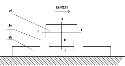
There are the following equations:
m - the total mass of the moving parts (kg);
G——gravitational acceleration (m/s2);
F r - the vertical attractive force between the stator and the mover (N);
F f —— frictional resistance
F - traction
μ——The friction coefficient of the guide rail.
a - the acceleration of the feed motion (m/s2).
Because the stroke is usually short when printing, the speed of the linear motor movement - the time curve is a triangle.
l Estimate by a linear motor with a core.
Estimation of some parameters:
Total mass of moving parts: nozzle module (3KG) + motor mover and guide rail corresponding load (7KG).
The coefficient of friction is 0.004
Maximum thrust value required at start-up
Maximum thrust value required when braking
Rated thrust value at constant speed (constant speed time is 0)
Then the system root mean square effective thrust value is:
l Estimated by linear motor without iron core
Fr=0
G will take a small G=75N
Maximum thrust value required at start-up
Maximum thrust value required when braking
Then the system root mean square effective thrust value is:
Second, Y-axis motor calculation:
Y stroke: 200mm
Total load: 12kg
Y maximum speed: 1m / s
Y maximum acceleration: 1g
Ibid.
l Estimate by a linear motor with a core.
Estimation of some parameters:
Total mass of moving parts: 12KG.
The coefficient of friction is 0.004
Maximum thrust value required at start-up
Maximum thrust value required when braking
Rated thrust value at constant speed (constant speed time is 0)
Then the system root mean square effective thrust value is:
l When estimating by a linear motor without iron core, the change is not big.